
IS 800:2007 and IRC:24-2010 apply the same limit-state design philosophy to steel members — the formulations for tension, compression, bending and shear are essentially common — but the clause numbers, table numbers and page references are completely different. IS 800 is the general code for steel structures; IRC:24 is Section V of the IRC bridge code, written specifically for steel road bridges. A designer moving between a building project and a bridge project is not learning new mechanics. They are re-learning where to find the same equations.
That difference matters more than it sounds. Submissions get queried, and calculation sheets get sent back, because a designer cited IS 800 Clause 6.3.3 in a bridge report where the checking authority expected IRC:24 Clause 506.1.2.3 — for the identical rupture check. This article maps the two codes clause by clause for the checks a steel bridge designer uses most.
Key takeaways
- For steel road bridges in India, IRC:24-2010 is the governing code; IS 800:2007 governs general steel structures.
- The limit-state formulations for tension yielding, rupture, block shear, compression, bending and shear are substantially common to both codes.
- What changes is the numbering: IS 800 Section 6 (tension) maps to IRC:24 Clause 506, Section 7 (compression) to 507, Section 8 (bending) to 509, and Section 9 (combined shear and bending) to 510.
- Table references differ too — the imperfection factor table is Table 7 in IS 800 and Table 3 in IRC:24; the partial-safety-factor table is Table 5 versus Table 1.
- Always cite the code the checking authority expects for that structure class, and verify every clause number against the current edition in your office.
What this guide covers
1. Which code applies to which structure
IS 800:2007, General Construction in Steel – Code of Practice (Third Revision), is the Bureau of Indian Standards code for steel structures generally. It introduced limit state design as the primary method in Indian steel practice.
IRC:24-2010, Standard Specifications and Code of Practice for Road Bridges, Section V – Steel Road Bridges (Limit State Method), is the Indian Roads Congress code for steel road bridges. It carries the limit-state member-design provisions across into the bridge context, alongside bridge-specific matters — fatigue, load combinations from IRC:6, and detailing for bridge components — that IS 800 does not address in the form a bridge needs.
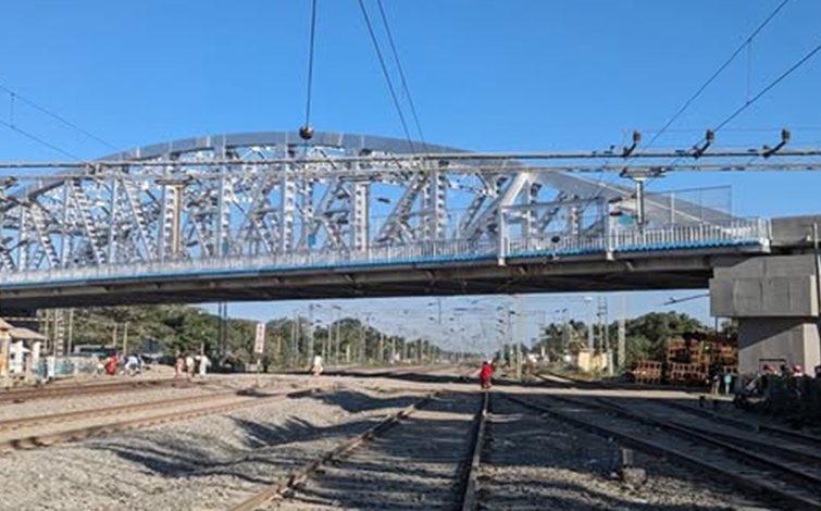
The practical rule. For a steel road bridge, girder, ROB or flyover superstructure, cite IRC:24 and its clause numbers, with IRC:6 for loads. Use IS 800 where IRC:24 is silent, or for ancillary steelwork that is not part of the bridge proper — and say so explicitly in the calculation sheet when you do. Mixing citations without stating why is what generates queries.
2. Quick clause map: IS 800:2007 to IRC:24-2010
| Design check | IS 800:2007 | IRC:24-2010 |
|---|---|---|
| Tension member — general requirement (T ≤ Td) | Cl. 6.2 | Cl. 506.1 |
| Yielding of gross section (Tdg) | Cl. 6.2 | Cl. 506.1.1 |
| Rupture of critical section (Tdn) | Cl. 6.3.3 | Cl. 506.1.2.3 |
| Block shear (Tdb) | Cl. 6.4.1 | Cl. 506.1.3.1 |
| Partial safety factor table (γm0, γm1) | Table 5 | Table 1 |
| Compression member — design strength (Pd = Ae·fcd) | Cl. 7.1.2 | Cl. 507.1.2 |
| Design compressive stress fcd | Cl. 7.1.2.1 | Cl. 507.1.2.1 |
| Imperfection factor α | Table 7 | Table 3 |
| Bending — laterally supported beam | Cl. 8.2 | Cl. 509.2 |
| Md where V ≤ 0.6 Vd | Cl. 8.2.1.2 / 8.2.1.3 | Cl. 509.2.1.2 |
| Mdv where V > 0.6 Vd (high shear) | Cl. 8.2.1.3, read with Cl. 9.2.2 | Cl. 509.2.1.3, read with Cl. 510.2 |
| Bending — laterally unsupported beam | Cl. 8.2.2 | Cl. 509.2.2 |
| Bending stress reduction factor χLT, elastic critical moment Mcr | Cl. 8.2.2, Table 13 | Cl. 509.2.2, Table 10 |
| Effective length for lateral torsional buckling (LLT) | Cl. 8.3.1, Table 15 | Cl. 509.2.2, Table 10a |
| Design shear strength (Vd = Vn/γm0) | Cl. 8.4 | Cl. 509.4 |
| Nominal plastic shear resistance (Vp) | Cl. 8.4.1 / 8.4.1.1 | Cl. 509.4.1 / 509.4.1.1 |
| Resistance to shear buckling | Cl. 8.4.2 | Cl. 509.4.2 |
Clause mapping compiled from side-by-side working notes on IS 800:2007 and IRC:24-2010. Verify each number against the current edition of the code held in your office before using it in a submission — clause numbering has shifted across revisions of both codes.
3. Design of tension members
Both codes state the same governing requirement: the factored design tension T in the member shall satisfy T ≤ Td, where Td is the design strength of the member, taken as the lowest of three values.
3.1 Yielding of the gross section
Tdg = Ag · fy / γm0
where Ag is the gross area of cross-section, fy the yield stress of the material, and γm0 the partial safety factor for failure governed by yielding. IS 800 takes γm0 from Table 5; IRC:24 from Table 1.
3.2 Rupture of the critical section
Tdn = 0.9 Anc fu / γm1 + β Ago fy / γm0
with the shear lag factor
β = 1.4 − 0.076 (w/t)(fy/fu)(bs/Lc) ≥ 0.7
and an upper bound of (fu γm0)/(fy γm1). The approximate net-section value for preliminary sizing is Tdn = α An fu/γm1. IS 800 places this at Clause 6.3.3; IRC:24 at Clause 506.1.2.3.
3.3 Block shear
Block shear strength Tdb is taken as the lesser of:
- Tdb = [Avg fy / (√3 γm0)] + 0.9 Atn fu / γm1
- Tdb = [0.9 Avn fu / (√3 γm1)] + Atg fy / γm0
IS 800 Clause 6.4.1; IRC:24 Clause 506.1.3.1.
The design strength Td is the lowest of the three, and the efficiency of the member — η = Tdg/Td — tells you immediately which limit state is controlling. An efficiency well below one on a tension member almost always points to the connection, not the section: too few bolts in line, an inadequate connection length Lc, or a gusset detail driving block shear. That is a detailing fix, not a heavier member.
4. Design of compression members
The design compressive strength of a member is given in both codes as:
Pd = Ae · fcd
where Ae is the effective sectional area and fcd the design compressive stress, subject to P ≤ Pd. IS 800 Clause 7.1.2; IRC:24 Clause 507.1.2.
The design compressive stress follows the Perry–Robertson form used across both codes:
fcd = (fy/γm0) / [φ + (φ² − λ²)0.5] = χ fy/γm0 ≤ fy/γm0
with
- φ = 0.5 [1 + α(λ − 0.2) + λ²]
- λ = non-dimensional effective slenderness ratio = √(fy/fcc) = √[fy(KL/r)²/π²E]
- fcc = Euler buckling stress = π²E/(KL/r)²
- χ = stress reduction factor = 1/[φ + (φ² − λ²)0.5]
- α = imperfection factor, corresponding to the buckling class of the section
The mechanics are identical. The imperfection factor table is where the numbering diverges: IS 800 gives α in Table 7; IRC:24 gives it in Table 3. This is one of the most common transcription errors in mixed-source calculation sheets, because both tables are short, look similar, and are keyed to buckling class rather than to section designation.
Our free steel I-section and composite section designer and steel box section designer carry out these checks directly, and the section properties calculator is useful for getting Ae, Iy and r right before you start.
Get a technical opinion on your project
Design, DPR, proof checking and independent review for highway and bridge projects across India.
5. Design strength in bending
5.1 Laterally supported beams
Where the compression flange is restrained, the factored design moment M must satisfy M ≤ Md. The value of Md depends on whether the section is also carrying high shear.
Case (i): low shear, V ≤ 0.6 Vd
- Md = βb Zp fy/γm0
- with Md ≤ 1.2 Ze fy/γm0 for a simply supported beam
- and Md ≤ 1.5 Ze fy/γm0 for a cantilever
where βb = 1.0 for plastic and compact sections, and Zp/Ze for semi-compact sections. IS 800 Clause 8.2.1.2/8.2.1.3; IRC:24 Clause 509.2.1.2.
Case (ii): high shear, V > 0.6 Vd
The moment capacity is reduced to Mdv:
- For plastic and compact sections: Mdv = Md − β(Md − Mfd) ≤ 1.2 Ze fy/γm0, with β = (2V/Vd − 1)²
- For semi-compact sections: Mdv = Ze fy/γm0
where Mfd is the plastic design strength of the area of cross-section excluding the shear area, considering the partial safety factor γm0. IS 800 Clause 8.2.1.3 read with Clause 9.2.2; IRC:24 Clause 509.2.1.3 read with Clause 510.2.
5.2 Laterally unsupported beams
Where the compression flange is not restrained, the design bending strength becomes:
Md = βb Zp fbd
with fbd = χLT fy/γm0, and the bending stress reduction factor
χLT = 1/{φLT + [φLT² − λLT²]0.5} ≤ 1.0
φLT = 0.5 [1 + αLT(λLT − 0.2) + λLT²]
where αLT is the imperfection parameter for lateral torsional buckling, distinguishing rolled from welded sections, and
λLT = √(βb Zp fy/Mcr) ≤ √(1.2 Ze fy/Mcr) = √(fy/fcr,b)
For a simply supported prismatic member, the elastic critical moment is:
Mcr = (π² E Iy hf / 2 LLT²) · {1 + (1/20)[(LLT/ry)/(hf/tf)]²}0.5 = βb Zp fcr,b
and for a prismatic member made of a standard rolled I-section, fcr,b is read directly from IS 800 Table 13 or IRC:24 Table 10. Here:
- It = torsional constant = Σ bi ti³/3 for an open section
- Iw = warping constant
- Iy, ry = moment of inertia and radius of gyration about the weak axis
- LLT = effective length for lateral torsional buckling, taken from IS 800 Clause 8.3.1 Table 15, or IRC:24 Table 10a under Clause 509.2.2
6. Design shear strength and web buckling
6.1 Nominal plastic shear resistance
The factored design shear force V must satisfy V ≤ Vd, where Vd = Vn/γm0. For plastic shear resistance, Vn = Vp, with
Vp = Av fyw / √3
where Av is the shear area and fyw the yield strength of the web. IS 800 Clause 8.4/8.4.1; IRC:24 Clause 509.4/509.4.1.
The shear area Av depends on the section and the axis of bending:
| Section | Bending about | Shear area Av |
|---|---|---|
| I and channel, hot rolled | Major axis | h · tw |
| I and channel, welded | Major axis | d · tw |
| I and channel, hot rolled or welded | Minor axis | 2 b tf |
| Rectangular hollow section, uniform thickness | Loaded parallel to depth (h) | A h / (b + h) |
| Rectangular hollow section, uniform thickness | Loaded parallel to width (b) | A b / (b + h) |
| Circular hollow tube, uniform thickness | — | 2 A / π |
| Plates and solid bars | — | A |
6.2 Resistance to shear buckling
Shear buckling of the web must be checked when the web slenderness exceeds the code limit:
- d/tw > 67ε — for a web without stiffeners
- d/tw > 67ε √(Kv/5.35) — for a web with transverse stiffeners
where ε = √(250/fy) and Kv is the shear buckling coefficient:
- Kv = 5.35 when transverse stiffeners are provided only at supports
- Kv = 4.0 + 5.35/(c/d)² for c/d < 1.0
- Kv = 5.35 + 4.0/(c/d)² for c/d ≥ 1.0
with c and d the spacing of transverse stiffeners and the depth of the web respectively. IS 800 Clause 8.4.2; IRC:24 Clause 509.4.2.
For the simple post-critical method, the nominal shear strength Vn = Vcr = Av τb, where τb is the shear stress corresponding to web buckling:
- τb = fyw/√3 when λw ≤ 0.8
- τb = [1 − 0.8(λw − 0.8)] (fyw/√3) when 0.8 < λw < 1.2
- τb = fyw/(√3 λw²) when λw ≥ 1.2
and the non-dimensional web slenderness ratio for shear buckling is
λw = √[fyw / (√3 τcr,e)]
with the elastic critical shear stress of the web
τcr,e = Kv π² E / [12 (1 − μ²)(d/tw)²]
where μ is Poisson's ratio.
7. What this means in practice
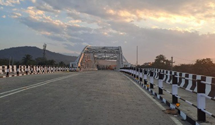
- Pick one code as the basis and state it on the cover sheet. For a steel road bridge that is IRC:24-2010 with IRC:6 loads. Anywhere you fall back on IS 800, say so and say why.
- Do not copy clause numbers across from a building job. The equations survive the move; the references do not. Clause 6.3.3 in a bridge report is a query waiting to happen.
- Watch the table numbers, not just the clause numbers. The imperfection factor (Table 7 versus Table 3), the partial safety factors (Table 5 versus Table 1) and the effective length for lateral torsional buckling (Table 15 versus Table 10a) are the three most commonly mis-cited.
- Remember what IRC:24 adds. Fatigue, bridge-specific load combinations and component detailing are the reason IRC:24 exists as a separate document. The member-design clauses covered here are only part of what a bridge submission has to satisfy.
- Verify against the edition in your office. Both codes have been revised, and a clause number quoted from memory or from an old set of notes is the single most avoidable error in a steel design submission.
For steel superstructure design, proof checking or a second opinion on a member-check methodology, see our ROB and RUB design and elevated and flyover structures practice areas, the wider detailed engineering services, or the full set of free structural design tools.
On the same theme of getting the codal trail right in a submission, see our companion guides to IRC and IS codes for bridge hydrology and hydraulics and to preparing a bridge and cross-drainage structures inventory.
8. Frequently asked questions
What is the difference between IS 800 and IRC:24?
IS 800:2007 is the general Bureau of Indian Standards code for construction in steel; IRC:24-2010 is Section V of the IRC road bridge code, covering steel road bridges by the limit state method. The member-design formulations for tension, compression, bending and shear are substantially common, but the clause and table numbering differs, and IRC:24 additionally covers bridge-specific matters such as fatigue and bridge load combinations.
Which code should be used for steel bridge design in India — IS 800 or IRC:24?
IRC:24-2010 governs steel road bridges, read with IRC:6 for loads and load combinations. IS 800:2007 is used where IRC:24 is silent, or for ancillary steelwork that is not part of the bridge proper. The code basis should be stated explicitly on the calculation cover sheet, and any fallback to IS 800 should be identified where it occurs.
Which IRC:24 clause corresponds to IS 800 Clause 6.3.3?
IS 800:2007 Clause 6.3.3, covering design strength due to rupture of the critical section in a tension member, corresponds to IRC:24-2010 Clause 506.1.2.3. Similarly, IS 800 Clause 6.2 (yielding of gross section) maps to IRC:24 Clause 506.1.1, and IS 800 Clause 6.4.1 (block shear) maps to IRC:24 Clause 506.1.3.1.
How is the design tensile strength of a member calculated?
The design strength Td is the lowest of three values: yielding of the gross section, Tdg = Agfy/γm0; rupture of the critical section, Tdn, computed with the shear lag factor β; and block shear, Tdb. The ratio Tdg/Td gives the efficiency of the member and identifies which limit state is controlling.
When must shear buckling of the web be checked?
Shear buckling must be checked when d/tw exceeds 67ε for an unstiffened web, or 67ε√(Kv/5.35) for a web with transverse stiffeners, where ε = √(250/fy). The check is at IS 800 Clause 8.4.2 and IRC:24 Clause 509.4.2.
What happens to the moment capacity when shear is high?
When the factored shear force exceeds 0.6 Vd, the moment capacity is reduced to Mdv. For plastic and compact sections, Mdv = Md − β(Md − Mfd) with β = (2V/Vd − 1)², capped at 1.2 Zefy/γm0; for semi-compact sections, Mdv = Zefy/γm0. See IS 800 Clause 8.2.1.3 with 9.2.2, or IRC:24 Clause 509.2.1.3 with 510.2.
Is IRC:24-2010 a limit state code?
Yes. IRC:24-2010 is titled Steel Road Bridges (Limit State Method) and applies limit state design, replacing the working stress approach of the earlier edition. This is why its member-design provisions align closely with IS 800:2007, which introduced limit state design as the primary method for steel structures in India.
9. References
- IS 800:2007, General Construction in Steel – Code of Practice (Third Revision), Bureau of Indian Standards.
- IRC:24-2010, Standard Specifications and Code of Practice for Road Bridges, Section V – Steel Road Bridges (Limit State Method), Indian Roads Congress.
- IRC:6, Standard Specifications and Code of Practice for Road Bridges, Section II – Loads and Load Combinations, Indian Roads Congress.
- IRC:22, Standard Specifications and Code of Practice for Road Bridges, Section VI – Composite Construction, Indian Roads Congress.
Disclaimer: This comparison is prepared from working notes for engineering-practice reference and paraphrases the intent of the cited provisions. It is not a substitute for the complete current text of IS 800:2007 or IRC:24-2010. Clause numbers, table numbers and numerical coefficients must be verified against the current edition of each code before use in any design submission.